
The American iconic MBT
The M1 Abrams eclipsed for the last thirty years all past MBTs to date, including the M48/M60 series. It represented a definitive change in US tank design since World War 2 and was engineered with the crew protection in mind, but without sacrificing either the firepower or mobility. Since numerous reports from the 1973 Yom Kippur war were carefully dissected, this was expressed inside NATO as the “air-land battle” concept in 1976, formulated in 1982 as the AirLand Battle Doctrine, which emphasised adequate combinations of land and air power to deal with a considerable fleet of soviet tanks with increased lethality. The future tank was to be capable of tactical superiority on the battlefield in order to compensate for the numerical inferiority.
The approach taken by the Army staff was not to build the best tank overall, but to reach any objectives within the lowest budget possible. Since any MBT is a compromise, the process was not simple, and the Army chose to play for a competitive process, each company trying the best possible tank design for a development at the lowest cost. The two companies chosen were without surprise, Chrysler Corporation (builder of the M60) and the General Motors Corporation (builder of the MBT-70).
Eventually, the M1 proved its excellence in combat, during the first Persian gulf war (1991), and the post nine-eleven operations in Afghanistan and Irak. In all these operations, the M1 reigned supreme and washed over any armored opposition with apparent ease, earning a solid reputation as one of the world’s very best MBTs.
Design
Hull
The hull is made of solid RHA, a single block made of massive parts welded together (bottom, front beak, glacis plate, sides, rear plate), with compartmentation. The driver is located in the front center, at the feet of the turret ring, with three periscopes (see later) and a one-piece hatch which can be opened at any time in regards to the turret. The particular hull front is composed of a beak sloped downwards, which joined an almost vertical glacis plate up to the turret. The hull armor is made of RHA but the turret was made of a composite armor. There is a characteristic rear hull elevation to house the turbine engine. The sides are flat, but tooling storage is assumed by the turret’s sides and rear baskets and bins.
Crew protection inside the tank comprised the halon automatic fire extinguisher system. In addition, smaller hand-held fire extinguishers are also provided. The engine compartment’s one is engaged by pulling a T-handle located on the left side of the tank. Fuel and ammunition are safely stored in armored compartments with blowout panels to prevent the ammo from “cooking off” if damaged, and the main gun’s ammunition is stored in the turret rear with blast doors which opens and slides automatically when ejecting a spent round. The tank is fully NBC-proven with a special lining, a 200 SCFM clean conditioned air system, a Radiac Radiological Warning Device AN/VDR-1 and a chemical agent detector, in addition to the crew’s protective suits and face masks.
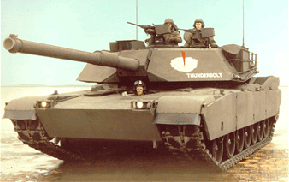
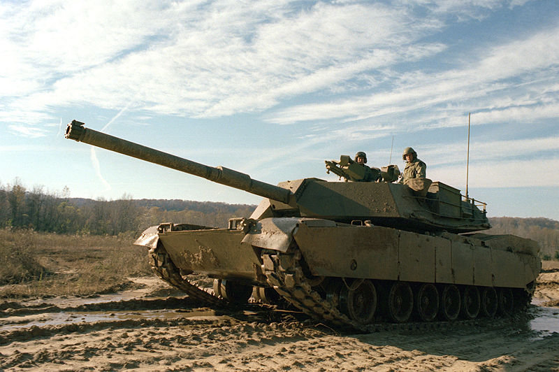
XM1 Abrams “Thunderbolt” of the first series in 1978. Credits: General Dynamics.
Propulsion
The big heart of the Abrams, siege of unparalleled performances, is the Lycoming AGT 1500 multi-fuel gas turbine (later manufactured by Honeywell) capable of delivering 1,500 shaft horsepower (1,100 kW). It was served by a six-speed (four forward, two reverse) Allison X-1100-3B Hydro-Kinetic automatic transmission. Top speed was 45 mph (72 km/h) on paved roads, and 30 mph (48 km/h) cross-country with a governor, but up to 60 mph (97 km/h) on road with the engine governor removed, which was way ahead of the M60 and M48, and equalled the Christie “race tank” performances back in 1930. However in operations, to prevent any damage to the drivetrain and shock injuries for the crew, a cruising speed of just above 45 mph (72 km/h) was maintained. The engine is multifuel according to NATO’s standards, accepting diesel, kerosene, motor gasoline and even high-octane jet fuel like JP-4/8. For logistical reasons, the JP-8 is preferred by the US military.
This gas turbine was proven quite reliable in practice and in combat conditions but was soon hampered by its equally high fuel consumption, ending in a serious logistic issue. Starting the turbine alone consumed no less than 10 US gallons (38 L) of fuel, and was rated for 1.67 US gallons (6.3 L) for each mile or 60 US gallons (230 L) per hour on flat, much more cross-country and even to 10 US gallons (38 L) when idle. The use of a mine plough could increase these numbers by 25 percent. The M1 uses around 300 gallons in 8 hours for a sustained usage which can depend on the missions specifics, terrain and weather. The refueling process of a single tank takes about 10 minutes and rearming, in addition, a full tank platoon can take around 30 minutes under ideal conditions and with a trained crew. Not surprisingly it is the Achilles heel of the Abrams, restricting its operational range.
M1 Abrams Lycoming LGT 1500 turbine schematics. Credits: General Dynamics.
Moreover, the turbine own’s high-speed & temperature, equalling a jet blast from the rear prevented the infantry to follow the tank closely, an issue especially in urban combat. However it was very quiet compared to diesel engines, with less resonance when perceived from afar. For this, the M1 was nicknamed “whispering death” during its first REFORGER exercise in Germany.
This power was transferred to the ground by a set of seven doubled ruberrized roadwheels (per side) suspended by torsion arms. The first pair was further apart to the front. Another pair acted as tensioners. The High-hardness-steel torsion bars were given rotary shock absorbers and provided an even smoother ride than the M60, while being still compatible with the general ordnance and less complex mechanically, easier to maintain than the original hydropneumatic system. The tracks were of the RISE standard for durability.
The driver is laying low in his seat due to the hull’s gacis extreme angle and Reclining. He has at his disposal a full station displaying the condition of vehicle with fluid levels, batteries and electrical equipment (now digitalized) and in some cases a steer-to indicator to find the best tactical route. He can scan for the best ground and the protection offered by the terrain through a set of three observation periscopes (or two and a central image intensifyer for night vision and poor visbility in general; dust, snow, heavy rain, fog…), covering a 120° frontal arc. This AN/VSS-5 image intensifier is developed by Texas Instruments, based on a 328 x 245 element uncooled detector array, working in the 7.5 to 13 micron waveband.
Turret
For the first time, the Turret was designed from the beginning to operate a laser range finder, a ballistic computer, a gunner thermal-imaging day and night sight, a muzzle reference sensor to measure the gun-tube distortion and a wind sensor. It was a real leap forward compared to previous generations. The crew of three take place inside the central inner turret, with a standard loader instead of an autoloader. The latter was a uniquely shaped pentagram, with a sloped faceted nose, flat sides and rear. Fastening equipments took place all over. The turret was in fact much smaller, but with side composite armour blocks that acted as massive extensions. This was already a modular compartimentation, although the blocks were welded and not just held in place by brackets. The two cupolas (commander to the right and loader to the left) are side by side.
The turret is fitted with 2×6 L8A1 (M250) smoke grenade launchers (2×8 for the USMC version) blocking both vision and thermal imaging, and in support a smoke generator triggered by the driver. This system is well known. Fuel is injected into the hot turbine exhaust, creating a massive smoke cloud. But because of the JP-8 used more commonly, this possibility was disabled due to the risk of fire damage in the engine compartment.
Active protection consists of the the AN/VLQ-6 Missile Countermeasure Device (MCD) Softkill Active protection system, mounted on the turret, in front of the loader’s hatch. It is box-shaped and fixed into position. The MCD can disrupt SACLOS guidance systems, wire and radio guided ATGMs. It could also thermally blur the infrared image with a condensed, massive emission that confuse the IR view or any targeting acquisition system, when detected, and the missile is left to detonate elsewhere.
A view of the gunner’s station (bottom left) and commander station (top right). Credits US Army, public domain.
Gunner
He is situated in the right hand side of the turret, in front of the commander seat. His Primary Sight-Line of Sight GPS-LOS is manufactured by the Electro-Optical Systems Division of Hughes Aircraft Company. It is a single axis stabilized head mirror. Daylight optics has a x10 narrow x3 wide magnification wide field of view on 18 degrees at close range. The night vision Thermal Imaging System has a x10 narrow/ x3 wide agnification field of view. It is a part of the eyepiece of the gunner’s sight, coupled with the range measurement provided by the laser range finder. The two-axis GPS-LOS provides an increased first round hit probability due to fast target acquisition & gun pointing, with a stabilization accuracy/bore sight retention less than 100 microrads. His secondary sight is a Kollmorgen Model 939 with a magnification x8/8°.
Laser rangefinder
The Hughes LR is composed of a neodinium yttrium aluminium garnet (Nd:YAG), a laser transmitter, and a receiver. Data transferred and integrated into the FCS in real time. The laser beam reflection provides a time of travel for accurate range measurement with a wavelength of 1.06 microns. The upgraded laser rangefinder includes a Raman resonator decreasing the wavelenght to 1.54 microns, safe for the eye. The laser beam could be emitted at a rate of 1 shot per second. It is accurate within a 32 feets (10 m) margin and target discrimination of 65 feets (20 m).
Fire Control System
The FCS computer is manufactured by Computing Devices Canada (Ontario). It is composed of an electronics unit, data entry, and test panel. The range data is transferred to computer that calculate the fire control solution. This data includes the lead angle measurement, bend of the gun, wind velocity crossed with data from a pendulum static cant sensor (center of the turret roof). Manual Inputs to the FCS are the ammunition type, temperature and barometric pressure.
Commander
The commander cupola (right hand side) gets six vision blocks for a 360° panoramic view, a day/night sight periscope with range is -12 to +20° in elevation, with 360 degrees in azimuth and a x2.6 at 3.4° narrow field of view magnification up to x7.7 at 10.4° wide magnification. He can also scan his tank interior condition via the inter vehicular information system (IVIS) and in some cases an appliqué digital screen. He also have an automatic sector scanning, and an automatic target cueing of the gunner’s sight and back-up fire control in case. The commander has a gyrostabilized head for sensors and a hand control grip to selecting parameter settings on a panel, an electronics unit with a remote cathode ray tube display. Usually the system is tailored for the commander to spot the target, then digitally pass the information to the gunner and main FCS that directs the fire, while the commander is already picking the coordinates of the next target. With such flow, it is estimated that the Abrams can neutralize ten targets in the matter of 30 seconds.
XM-1 in demonstration at Fort Knox, Kentucky 1979. Credits US Army, public domain.
Loader
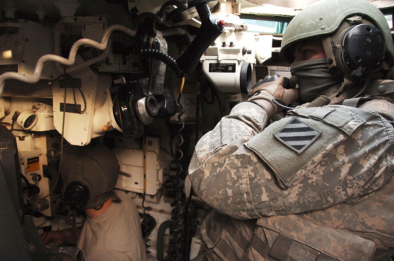
He is seated on the left hand side of the main armament, with a simple two-pieces hatch over him. Inside the turret, he is responsible for loading the main gun with ready rounds (and supplying new ones) and serving the coaxial M240 7.62 mm light machine gun, placed on the right hand side of the main gun. Outside the turret, he could use a secondary 7.62 caliber M240 machine gun placed on a Skate mount. It has a -30 to +65° elevation and 265° traverse. He is well placed inside the tank to vizualise the digital displays and generally scan for targets and antitank guided missile (ATGM), using the detection sensors and activating/maintaing the AN/VLQ-6 MCD active protection system.
Armour
The Ballistics Research Laboratory at Aberdeen Proving Grounds began a crash program for a Chobham-inspired armour in 1978, and the first production M1 in 1981 weighed about sixty tons fully loaded, combining a normal RHA steel armour under a new composite special armor (layers of both steel and composites, heat and shock absorbing materials), proven against any sorts of HEAT and kinetic energy penetrators. The general scheme is derived from the “Burlington” armour tested on the Chieftain. It is a multi-layered armour combining various alloys of steel, sandwiched with ceramics and plastic composites, including kevlar. The order of these layers and relative thickness are top secret and classified. The whole has an equivalent of 1,320–1,620 millimetres (52–64 in) of RHA on the turret front against all chemical energy rounds, and 940–960 mm (37–38 in) for kinetic energy penetrators (APFSDS or “sabot” rounds). The M1 also tried in operations reactive armor over the track skirts to defeat RPGs, mostly encountered in an urban environment, or slat armor (rear and rear fuel cells) against ATGMs. A Kevlar liner prevents any spalling.
Armament
The very core of the early Abrams was its M60A1 105 mm rifled gun, similar to the one used by both the M60 and the upgraded M48, and licence built after the original British Royal Ordnance L7 gun. The turret is however tailored to accept the German Rheinmetall 120mm gun if necessary. With the advent of more advanced 105 mm rounds like the DU penetrator M833 round, it was possible to delay gun upgrade until 1985 (M1A1), despite the arrival of the T-64 and T-72 in the Soviet arsenal, both armed with 120+ mm guns, in addition to the T-62. The improved M883 round was indeed capable of penetrating 420mm of RHA at 60° at 2,000 meters.
This gun can fire the large variety of ammunitions in use within NATO, including the following series:
Secondary armament comprised a combination of 0.3 and 0.5 caliber machine guns, all located in the turret.
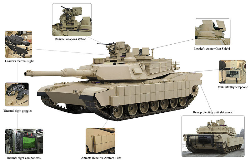
The turret top receive the traditional “Madeuce” .50 cal. (12.7 mm) M2HB in front of the commander’s hatch, mounted on the Commander’s Weapons Station, allows it to be aimed and fired from within the tank. With the introduction of the Common Remote Operated Weapons System (CROWS) kit, the M2A1 HMG, M240, or M249 SAW could be adapted to a remote weapons platform (similar to the one used on the Stryker). Transparent gun shields are also prvided, on the TUSK variant. The M1A1 Abrams Integrated Management (AIM) add a thermal sight for night and low-visibility shooting.
A 7.62 mm M240 machine gun in placed in front of the loader’s hatch (right-placed skate mount). Some were later fitted with gun shields during the Iraq War, and night-vision scopes for low-visibility and night fighting. The second M240 LMG is in a coaxial mount to the right of the main gun, and fired with the same computer and FCS which operates the main gun. An optional second coaxial 12.7 mm M2HB could be mounted directly above the main gun in a remote weapons platform (TUSK upgrade kit).
M1A1 interior cutaway. Credits: General Dynamics.
The M1IP or IPM1 (1984)
Operators
Australia

Egypt

Iraq

Kuwait

Morroco

Saudi Arabia

United States

The M1 Abrams eclipsed for the last thirty years all past MBTs to date, including the M48/M60 series. It represented a definitive change in US tank design since World War 2 and was engineered with the crew protection in mind, but without sacrificing either the firepower or mobility. Since numerous reports from the 1973 Yom Kippur war were carefully dissected, this was expressed inside NATO as the “air-land battle” concept in 1976, formulated in 1982 as the AirLand Battle Doctrine, which emphasised adequate combinations of land and air power to deal with a considerable fleet of soviet tanks with increased lethality. The future tank was to be capable of tactical superiority on the battlefield in order to compensate for the numerical inferiority.
The approach taken by the Army staff was not to build the best tank overall, but to reach any objectives within the lowest budget possible. Since any MBT is a compromise, the process was not simple, and the Army chose to play for a competitive process, each company trying the best possible tank design for a development at the lowest cost. The two companies chosen were without surprise, Chrysler Corporation (builder of the M60) and the General Motors Corporation (builder of the MBT-70).
Eventually, the M1 proved its excellence in combat, during the first Persian gulf war (1991), and the post nine-eleven operations in Afghanistan and Irak. In all these operations, the M1 reigned supreme and washed over any armored opposition with apparent ease, earning a solid reputation as one of the world’s very best MBTs.
Design
Hull
The hull is made of solid RHA, a single block made of massive parts welded together (bottom, front beak, glacis plate, sides, rear plate), with compartmentation. The driver is located in the front center, at the feet of the turret ring, with three periscopes (see later) and a one-piece hatch which can be opened at any time in regards to the turret. The particular hull front is composed of a beak sloped downwards, which joined an almost vertical glacis plate up to the turret. The hull armor is made of RHA but the turret was made of a composite armor. There is a characteristic rear hull elevation to house the turbine engine. The sides are flat, but tooling storage is assumed by the turret’s sides and rear baskets and bins.
Crew protection inside the tank comprised the halon automatic fire extinguisher system. In addition, smaller hand-held fire extinguishers are also provided. The engine compartment’s one is engaged by pulling a T-handle located on the left side of the tank. Fuel and ammunition are safely stored in armored compartments with blowout panels to prevent the ammo from “cooking off” if damaged, and the main gun’s ammunition is stored in the turret rear with blast doors which opens and slides automatically when ejecting a spent round. The tank is fully NBC-proven with a special lining, a 200 SCFM clean conditioned air system, a Radiac Radiological Warning Device AN/VDR-1 and a chemical agent detector, in addition to the crew’s protective suits and face masks.

XM1 Abrams “Thunderbolt” of the first series in 1978. Credits: General Dynamics.
Propulsion
The big heart of the Abrams, siege of unparalleled performances, is the Lycoming AGT 1500 multi-fuel gas turbine (later manufactured by Honeywell) capable of delivering 1,500 shaft horsepower (1,100 kW). It was served by a six-speed (four forward, two reverse) Allison X-1100-3B Hydro-Kinetic automatic transmission. Top speed was 45 mph (72 km/h) on paved roads, and 30 mph (48 km/h) cross-country with a governor, but up to 60 mph (97 km/h) on road with the engine governor removed, which was way ahead of the M60 and M48, and equalled the Christie “race tank” performances back in 1930. However in operations, to prevent any damage to the drivetrain and shock injuries for the crew, a cruising speed of just above 45 mph (72 km/h) was maintained. The engine is multifuel according to NATO’s standards, accepting diesel, kerosene, motor gasoline and even high-octane jet fuel like JP-4/8. For logistical reasons, the JP-8 is preferred by the US military.
This gas turbine was proven quite reliable in practice and in combat conditions but was soon hampered by its equally high fuel consumption, ending in a serious logistic issue. Starting the turbine alone consumed no less than 10 US gallons (38 L) of fuel, and was rated for 1.67 US gallons (6.3 L) for each mile or 60 US gallons (230 L) per hour on flat, much more cross-country and even to 10 US gallons (38 L) when idle. The use of a mine plough could increase these numbers by 25 percent. The M1 uses around 300 gallons in 8 hours for a sustained usage which can depend on the missions specifics, terrain and weather. The refueling process of a single tank takes about 10 minutes and rearming, in addition, a full tank platoon can take around 30 minutes under ideal conditions and with a trained crew. Not surprisingly it is the Achilles heel of the Abrams, restricting its operational range.

M1 Abrams Lycoming LGT 1500 turbine schematics. Credits: General Dynamics.
Moreover, the turbine own’s high-speed & temperature, equalling a jet blast from the rear prevented the infantry to follow the tank closely, an issue especially in urban combat. However it was very quiet compared to diesel engines, with less resonance when perceived from afar. For this, the M1 was nicknamed “whispering death” during its first REFORGER exercise in Germany.
This power was transferred to the ground by a set of seven doubled ruberrized roadwheels (per side) suspended by torsion arms. The first pair was further apart to the front. Another pair acted as tensioners. The High-hardness-steel torsion bars were given rotary shock absorbers and provided an even smoother ride than the M60, while being still compatible with the general ordnance and less complex mechanically, easier to maintain than the original hydropneumatic system. The tracks were of the RISE standard for durability.
The driver is laying low in his seat due to the hull’s gacis extreme angle and Reclining. He has at his disposal a full station displaying the condition of vehicle with fluid levels, batteries and electrical equipment (now digitalized) and in some cases a steer-to indicator to find the best tactical route. He can scan for the best ground and the protection offered by the terrain through a set of three observation periscopes (or two and a central image intensifyer for night vision and poor visbility in general; dust, snow, heavy rain, fog…), covering a 120° frontal arc. This AN/VSS-5 image intensifier is developed by Texas Instruments, based on a 328 x 245 element uncooled detector array, working in the 7.5 to 13 micron waveband.
Turret
For the first time, the Turret was designed from the beginning to operate a laser range finder, a ballistic computer, a gunner thermal-imaging day and night sight, a muzzle reference sensor to measure the gun-tube distortion and a wind sensor. It was a real leap forward compared to previous generations. The crew of three take place inside the central inner turret, with a standard loader instead of an autoloader. The latter was a uniquely shaped pentagram, with a sloped faceted nose, flat sides and rear. Fastening equipments took place all over. The turret was in fact much smaller, but with side composite armour blocks that acted as massive extensions. This was already a modular compartimentation, although the blocks were welded and not just held in place by brackets. The two cupolas (commander to the right and loader to the left) are side by side.
The turret is fitted with 2×6 L8A1 (M250) smoke grenade launchers (2×8 for the USMC version) blocking both vision and thermal imaging, and in support a smoke generator triggered by the driver. This system is well known. Fuel is injected into the hot turbine exhaust, creating a massive smoke cloud. But because of the JP-8 used more commonly, this possibility was disabled due to the risk of fire damage in the engine compartment.
Active protection consists of the the AN/VLQ-6 Missile Countermeasure Device (MCD) Softkill Active protection system, mounted on the turret, in front of the loader’s hatch. It is box-shaped and fixed into position. The MCD can disrupt SACLOS guidance systems, wire and radio guided ATGMs. It could also thermally blur the infrared image with a condensed, massive emission that confuse the IR view or any targeting acquisition system, when detected, and the missile is left to detonate elsewhere.

A view of the gunner’s station (bottom left) and commander station (top right). Credits US Army, public domain.
Gunner
He is situated in the right hand side of the turret, in front of the commander seat. His Primary Sight-Line of Sight GPS-LOS is manufactured by the Electro-Optical Systems Division of Hughes Aircraft Company. It is a single axis stabilized head mirror. Daylight optics has a x10 narrow x3 wide magnification wide field of view on 18 degrees at close range. The night vision Thermal Imaging System has a x10 narrow/ x3 wide agnification field of view. It is a part of the eyepiece of the gunner’s sight, coupled with the range measurement provided by the laser range finder. The two-axis GPS-LOS provides an increased first round hit probability due to fast target acquisition & gun pointing, with a stabilization accuracy/bore sight retention less than 100 microrads. His secondary sight is a Kollmorgen Model 939 with a magnification x8/8°.
Laser rangefinder
The Hughes LR is composed of a neodinium yttrium aluminium garnet (Nd:YAG), a laser transmitter, and a receiver. Data transferred and integrated into the FCS in real time. The laser beam reflection provides a time of travel for accurate range measurement with a wavelength of 1.06 microns. The upgraded laser rangefinder includes a Raman resonator decreasing the wavelenght to 1.54 microns, safe for the eye. The laser beam could be emitted at a rate of 1 shot per second. It is accurate within a 32 feets (10 m) margin and target discrimination of 65 feets (20 m).
Fire Control System
The FCS computer is manufactured by Computing Devices Canada (Ontario). It is composed of an electronics unit, data entry, and test panel. The range data is transferred to computer that calculate the fire control solution. This data includes the lead angle measurement, bend of the gun, wind velocity crossed with data from a pendulum static cant sensor (center of the turret roof). Manual Inputs to the FCS are the ammunition type, temperature and barometric pressure.
Commander
The commander cupola (right hand side) gets six vision blocks for a 360° panoramic view, a day/night sight periscope with range is -12 to +20° in elevation, with 360 degrees in azimuth and a x2.6 at 3.4° narrow field of view magnification up to x7.7 at 10.4° wide magnification. He can also scan his tank interior condition via the inter vehicular information system (IVIS) and in some cases an appliqué digital screen. He also have an automatic sector scanning, and an automatic target cueing of the gunner’s sight and back-up fire control in case. The commander has a gyrostabilized head for sensors and a hand control grip to selecting parameter settings on a panel, an electronics unit with a remote cathode ray tube display. Usually the system is tailored for the commander to spot the target, then digitally pass the information to the gunner and main FCS that directs the fire, while the commander is already picking the coordinates of the next target. With such flow, it is estimated that the Abrams can neutralize ten targets in the matter of 30 seconds.

XM-1 in demonstration at Fort Knox, Kentucky 1979. Credits US Army, public domain.
Loader
He is seated on the left hand side of the main armament, with a simple two-pieces hatch over him. Inside the turret, he is responsible for loading the main gun with ready rounds (and supplying new ones) and serving the coaxial M240 7.62 mm light machine gun, placed on the right hand side of the main gun. Outside the turret, he could use a secondary 7.62 caliber M240 machine gun placed on a Skate mount. It has a -30 to +65° elevation and 265° traverse. He is well placed inside the tank to vizualise the digital displays and generally scan for targets and antitank guided missile (ATGM), using the detection sensors and activating/maintaing the AN/VLQ-6 MCD active protection system.
Armour
The Ballistics Research Laboratory at Aberdeen Proving Grounds began a crash program for a Chobham-inspired armour in 1978, and the first production M1 in 1981 weighed about sixty tons fully loaded, combining a normal RHA steel armour under a new composite special armor (layers of both steel and composites, heat and shock absorbing materials), proven against any sorts of HEAT and kinetic energy penetrators. The general scheme is derived from the “Burlington” armour tested on the Chieftain. It is a multi-layered armour combining various alloys of steel, sandwiched with ceramics and plastic composites, including kevlar. The order of these layers and relative thickness are top secret and classified. The whole has an equivalent of 1,320–1,620 millimetres (52–64 in) of RHA on the turret front against all chemical energy rounds, and 940–960 mm (37–38 in) for kinetic energy penetrators (APFSDS or “sabot” rounds). The M1 also tried in operations reactive armor over the track skirts to defeat RPGs, mostly encountered in an urban environment, or slat armor (rear and rear fuel cells) against ATGMs. A Kevlar liner prevents any spalling.
Armament
The very core of the early Abrams was its M60A1 105 mm rifled gun, similar to the one used by both the M60 and the upgraded M48, and licence built after the original British Royal Ordnance L7 gun. The turret is however tailored to accept the German Rheinmetall 120mm gun if necessary. With the advent of more advanced 105 mm rounds like the DU penetrator M833 round, it was possible to delay gun upgrade until 1985 (M1A1), despite the arrival of the T-64 and T-72 in the Soviet arsenal, both armed with 120+ mm guns, in addition to the T-62. The improved M883 round was indeed capable of penetrating 420mm of RHA at 60° at 2,000 meters.
This gun can fire the large variety of ammunitions in use within NATO, including the following series:
- high explosive anti-tank (HEAT)
- high explosive (HE)
- White phosphorus
- Anti-personnel (multiple flechette)
Secondary armament comprised a combination of 0.3 and 0.5 caliber machine guns, all located in the turret.
The turret top receive the traditional “Madeuce” .50 cal. (12.7 mm) M2HB in front of the commander’s hatch, mounted on the Commander’s Weapons Station, allows it to be aimed and fired from within the tank. With the introduction of the Common Remote Operated Weapons System (CROWS) kit, the M2A1 HMG, M240, or M249 SAW could be adapted to a remote weapons platform (similar to the one used on the Stryker). Transparent gun shields are also prvided, on the TUSK variant. The M1A1 Abrams Integrated Management (AIM) add a thermal sight for night and low-visibility shooting.
A 7.62 mm M240 machine gun in placed in front of the loader’s hatch (right-placed skate mount). Some were later fitted with gun shields during the Iraq War, and night-vision scopes for low-visibility and night fighting. The second M240 LMG is in a coaxial mount to the right of the main gun, and fired with the same computer and FCS which operates the main gun. An optional second coaxial 12.7 mm M2HB could be mounted directly above the main gun in a remote weapons platform (TUSK upgrade kit).

M1A1 interior cutaway. Credits: General Dynamics.
The M1IP or IPM1 (1984)
Operators
Australia
Egypt
Iraq
Kuwait
Morroco
Saudi Arabia
United States